Compliant Mechanisms Explained
What is a Mechanism?
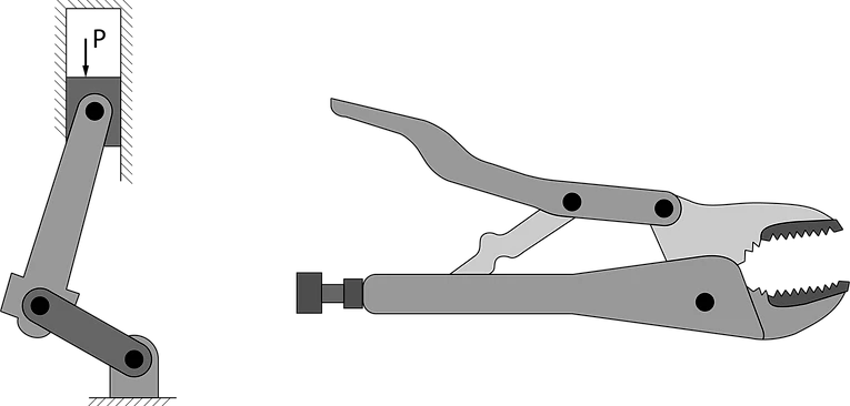
A mechanism is a mechanical device used to transfer or transform motion, force, or energy. Traditional rigid-body mechanisms consist of rigid links connected at movable joints. Two examples are shown below.
Compliant Mechanisms
A compliant mechanism is a mechanism that gains at least some of its mobility from the deflection of flexible members rather than from movable joints only. For the compliant crimping mechanism (shown below), the input force is transferred to the output port, much like the vice grips mechanism, only now some energy is stored in the form of strain energy in the flexible members. Note that if the entire device were rigid, it would have no mobility and it would be a structure.
Compliant mechanisms are all around us, from products we own to high-tech precision manufacturing equipment. You probably use many compliant mechanisms every day. Some examples include one-piece plastic lids (like the one on ketchup bottles), tape measures, battery clips, mouse buttons, and many snap-fit parts.

Advantages of Compliant Mechanisms
There are a number of reasons why a compliant mechanism may be considered for use in a particular application. Some of these advantages are listed below. Click on the titles to learn more.
-
Toggle ItemPart Count
One advantage of compliant mechanisms is the potential for a dramatic reduction in the total number of parts required to accomplish a specified task. The part count can be reduced by having flexible parts instead of springs, pins, and traditional rigid hinges. The number of components required for a compliant mechanism can be considerably less than for a rigid version of the same mechanism.
-
Toggle ItemProduction Processes
Compliant mechanisms can be simple to manufacture because they lend themselves well to various manufacturing processes. Because they get their motion from flexible regions, many compliant mechanisms can be fabricated flat from planar sheets of material. For example, the compliant grippers shown above can be fabricated from a single sheet of polypropelene. Compliant mechanisms can be manufactured using many methods including machining, stamping, a laser cutter, a water-jet cutter, 3D printing, and EDM.
-
Toggle ItemPrice
Because they have fewer parts and simple manufacturing processes, compliant mechanisms can be very inexpensive to manufacture. The reduction in part count may simplify manufacturing and reduce both the manufacturing and assembly time and cost. Compliant mechanisms can be simple to manufacture because they lend themselves well to various manufacturing processes. For example, some mechanisms may be manufactured from an injection-moldable material and constructed of one piece, as shown in the photo below.

-
Toggle ItemPrecise Motion
Traditional mechanisms can lose precision due to backlash and wear. Compliant mechanisms can allow precise motion by reducing or eliminating backlash and wear. Rigid-body mechanisms get their motion from physical pins and hinges sliding against one another. Mechanical wear happens when parts rub on one another as they move. Eventually this can rub away or modify the material, which effectively changes the geometry and movement of the mechanism. Because compliant mechanisms use bending material instead of traditional pins and rigid hinges, the wear can be greatly reduced (because no parts are rubbing on each other). Backlash is caused by the tolerances of interconnecting pieces. The backlash in compliant mechanisms may be reduced or eliminated because there are no (or fewer) interconnecting pieces. This fact has often been used in the design of instrumentation. Vibration and noise caused by the turning and sliding joints of rigid-body mechanisms may also be reduced in some applications by using compliant mechanisms.
-
Toggle ItemPerformance
Compliant mechanisms have a smaller number of movable joints, such as pin (turning) and sliding joints. This results in reduced friction and need for lubrication. These are valuable characteristics for applications where the mechanism is not easily accessible, or for operation in harsh environments that may adversely affect joints. This is especially important in space applications because lubricants tend to "outgas" (basically evaporate) in a low-gravity environment. The compliant pointer device, shown below, is a device that was specifically designed for use in space.

-
Toggle ItemProportions
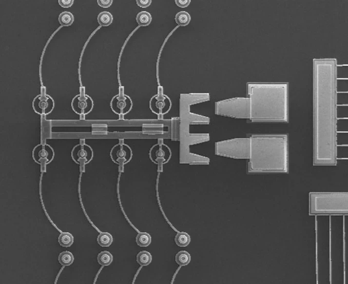
Another advantage of compliant mechanisms is the ease in which they are miniaturized . Simple micro structures, actuators, and sensors are seeing wide usage, and many other microelectromechanical systems (MEMS) show great promise. The reduction in the total number of parts and joints offered by compliant mechanisms is a significant advantage in the fabrication of micro mechanisms. Compliant micro mechanisms, like the one shown below, may be fabricated using technology and materials similar to those used in the fabrication of integrated circuits.
-
Toggle ItemPortability
It is possible to realize a significant reduction in weight by using a compliant mechanism over their rigid-body counterparts. This may be a significant factor in aerospace and other applications. Compliant mechanisms have also benefited companies by reducing the weight and shipping costs of consumer products.
-
Toggle ItemPredictability
Since compliant mechanisms rely on the deflection of flexible members, energy is stored in the form of strain energy in the flexible members. This stored energy is similar to the potential energy in a deflected spring, and the effects of springs may be integrated into a compliant mechanisms design. This can be used to easily store and/or transform energy to be released at a later time or in a different manner. A bow and arrow system is a simple example of this. Energy is stored in the limbs as the archer draws the bow. This potential energy is then transformed to kinetic energy of the arrow. These energy storage characteristics may also be used to design for specific force-deflection properties, or to cause a mechanism to tend to particular positions.
Challenges of Compliant Mechanisms
Just as there are a number of advantages associated with compliant mechanisms, there are also several challenges and disadvantages for some applications. Click on the titles to learn more.
-
Toggle ItemCombination of Complex Systems
Perhaps the largest challenge is the relative difficulty in analyzing and designing compliant mechanisms. Knowledge of mechanism analysis methods and the deflection of flexible members is required. The combination of the two bodies of knowledge in compliant mechanisms requires not only an understanding of both, but also an understanding of the interactions of the two in a complex system. The pseudo-rigid body model (discussed below) helps bridge this gap.
-
Toggle ItemNon-linear Equations
Since many of the flexible members undergo large deflections, linearized beam equations are no longer valid. Nonlinear equations must be used that account for the geometric nonlinearities caused by large deflections. Because of these difficulties, many compliant mechanisms in the past were designed by trial and error approaches. Such methods are only applicable for very simple systems that perform relatively simple tasks, and are often not cost efficient for many potential applications. Theory has been developed to simplify the analysis and design of compliant mechanisms and the limitations are not as great as they once were. Even considering these advances, however, compliant mechanism analysis and design is typically more difficult than for rigid-body mechanisms.
-
Toggle ItemEnergy Storage
Energy stored in flexible elements was discussed above as an advantage since it can be used to simplify mechanisms that incorporate springs, to obtain specified force-deflection relationships, and to store energy that is transferred or transformed by the mechanism. However, in some applications having energy stored in flexible members is a disadvantage. For example, if a mechanism's function is to transfer energy from the input to an output, not all of the energy is transferred since some is stored in the mechanism.
-
Toggle ItemFatigue
Fatigue analysis is typically a more vital issue for compliant mechanisms than for their rigid-body counterparts. Since compliant members are often loaded cyclically when a compliant mechanism is used, it is important to design those members such that they will have sufficient fatigue life to perform their prescribed functions.
-
Toggle ItemLimited Motion
The motion from the deflection of compliant links are also limited by the strength of the deflecting members. Obviously a compliant link cannot produce a continuous rotational motion such as that possible with a pin joint.
While these challenges may be overcome, it is important that the difficulties and limitations of compliant mechanisms are understood. Such knowledge is helpful in determining which applications will benefit the most by utilizing compliant mechanism technology.
Pseudo-Rigid Body Models
The pseudo-rigid-body model is used to simplify the analysis and design of compliant mechanisms. It is used to unify compliant mechanism and rigid-body mechanism theory by providing a method of modeling the nonlinear deflection of flexible beams. Click the titles below to learn more.

-
Toggle ItemThe Models Behind the Theory
This method of modeling allows well-known rigid-body analysis methods to be used in the analysis of compliant mechanisms (Salamon, 1989). Burns (1964) and Burns and Crossley (1968) approximated flexible couplers as a rigid link with a length five-sixths of the flexible segment. Howell and Midha (1993) analyzed compliant mechanisms with small-length flexural pivots. Since the lengths of the flexural members are small relative to the lengths of the rigid segments, the flexural pivots are modeled as kinematic joints at the center of the flexible segment. Torsional springs are used to represent the member stiffness. The accuracy of this method decreases as the relative length of the flexural member increases, and a different approach is required for compliant mechanisms containing longer flexural pivots. Below are a group of simple flexible members, described by pseudo-rigid-body models, as discussed above.
-
Toggle ItemHow the Model Works
Howell and Midha (1992) used closed-form elliptic-integral solutions to develop deflection approximations for an initially straight, flexible segment with linear material properties. The figure below shows such a member and its pseudo- rigid-body model. The model consists of two rigid links, connected by a "characteristic pivot" to represent the displacement, and a torsional spring to model the beam stiffness or resistance to the applied force. This model predicts the deflection path of the beam end for a given end load, to within 0.5% of the closed-form elliptic integral solutions for quite large deflections. The location of the characteristic pivot is expressed in terms of the "characteristic radius factor", gamma, which represents the fraction of the beam length at which the pivot is located. Once gamma is determined, the deflection path may be parameterized in terms of theta, the "pseudo-rigid-body angle."

-
Toggle ItemBenefits and Usage
Pseudo-rigid-body models for individual flexible segments offer a simplified method of determining the deflections of large-deflection members. The availability of such a method for individual segments suggests its use to model more complex systems which include flexible segments. This pseudo-rigid-body model concept proves to be very useful in simplifying the analysis and synthesis of compliant mechanisms. Its advantage lies in its ability to develop a pseudo-rigid-body model of a compliant mechanism, and then use the large body of knowledge available in the field of rigid-body mechanism analysis and design. In this way, the pseudo-rigid-body model concept acts to unify compliant and rigid-body mechanism theories. The image below shows another example of a compliant mechanism and its pseudo-rigid-body model.

In analysis, the kinematic motion, input requirements, and component stresses may be determined quickly and efficiently by means of the pseudo-rigid-body model. The greatest benefit of the pseudo-rigid-body model concept is realized in compliant mechanism design. In the early design stages, the pseudo-rigid-body model may serve as a fast and efficient method of evaluating many different trial designs to meet the specific design objectives. It also allows the design of systems to perform more complex tasks than would otherwise be possible. If a designer relies solely on prototyping or full numerical analysis, an initial design must be obtained before it can be modeled or built. The pseudo-rigid-body model, on the other hand, may be used to obtain a preliminary design which may then be optimized. Once a design is obtained such that it meets the specified design objectives, it may be further refined using methods such as nonlinear finite element analysis, and it may then be prototyped and tested. The development of design methods using the pseudo-rigid-body model is a priority of the research.